Onboard RGB LED
The ESP32-C5 board does not have a standard onboard LED. Instead, it has an addressable RGB LED connected to GPIO27. In a way, it is actually cool that our blinky program will be colorful. On the other side, for simple feedback where I use an onboard LED, I can’t use that simple way.
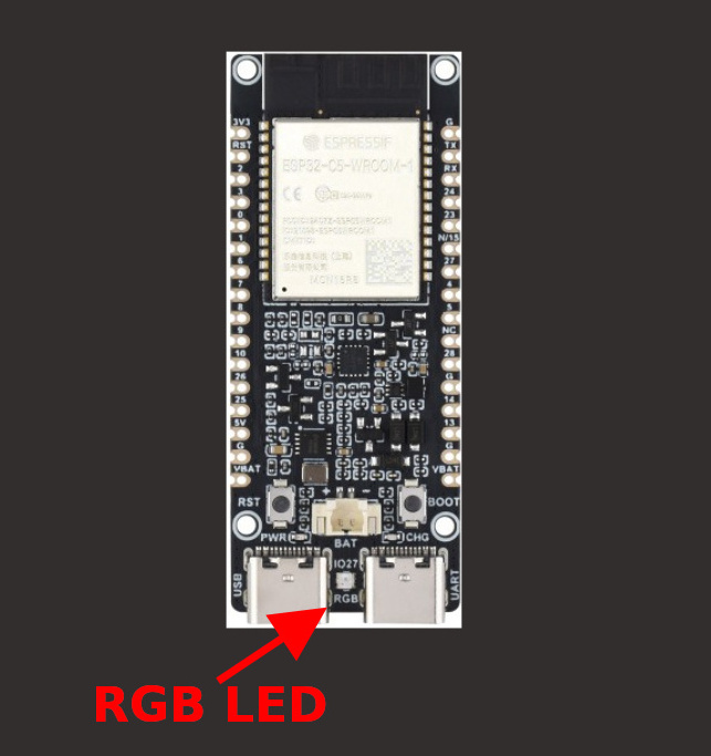
Let’s generate the project with esp-generate in headless mode.
esp-generate --headless -o esp32c5 -o defmt rgb-led
Dependencies
We will need two crates to work with the onboard RGB LED. The smart-leds crate provides a common interface for addressable LEDs such as WS2812 (NeoPixel) and APA102 (DotStar).
The esp-hal-smartled crate provides the ESP-HAL-specific implementation that uses the ESP32-C5’s RMT peripheral to generate the precise timing required by the WS2812B.
Add the following dependencies to your Cargo.toml:
esp-hal-smartled = "0.18.0"
smart-leds = "0.4.0"
Additional Imports
We will add the necessary imports. In future exercises, I may not add instructions to import when they are obvious. I always provide the finished project link, so you can check the imports there as well.
#![allow(unused)]
fn main() {
use esp_hal::rmt::Rmt;
use esp_hal::time::Rate;
use esp_hal::delay::Delay;
use esp_hal_smartled::{RmtSmartLeds, buffer_size, color_order};
use smart_leds::{RGB8, SmartLedsWrite};
}
Initialize RMT
First, let’s initialize the RMT peripheral. We will use an 80 MHz frequency.
#![allow(unused)]
fn main() {
let freq = Rate::from_mhz(80);
let rmt = Rmt::new(peripherals.RMT, freq).unwrap();
}
Configure the RGB LED
Next, we will configure the RMT channel to drive the WS2812B LED connected to GPIO27.
#![allow(unused)]
fn main() {
let mut led =
    RmtSmartLeds::<{ buffer_size::<RGB8>(1) }, _, RGB8, color_order::Grb>::new_with_memsize(
        esp_hal_smartled::WS2812_TIMING,
        rmt.channel0,
        peripherals.GPIO27,
        2,
        freq,
    )
    .unwrap();
}
The WS2812_TIMING provides the timing required by the WS2812B, while color_order::Grb specifies the order in which the LED expects the color values.
Main loop
Now we can use the write method to send RGB values to the LED. Let’s cycle through red, green, and blue with a 500 millisecond delay between each color.
#![allow(unused)]
fn main() {
 let delay = Delay::new();

loop {
    led.write([RGB8::new(255, 0, 0)]).unwrap();
    delay.delay_millis(500);

    led.write([RGB8::new(0, 255, 0)]).unwrap();
    delay.delay_millis(500);

    led.write([RGB8::new(0, 0, 255)]).unwrap();
    delay.delay_millis(500);
}
}
Clone the existing project
You can clone (or refer) project I created and navigate to the rgb-led folder.
git clone https://github.com/ImplFerris/esp32c5-projects
cd esp32c5-projects/rgb-led/
Run the program
Let’s flash the firmware and run it. If everything works, you should see the RGB LED cycle through red, green, and blue.
cargo run --release
I will avoid repeating this step in future exercises. If an exercise requires additional input, such as an environment variable, I will include the required command at that point.